What's new
Photoshop Gurus Forum

Welcome to Photoshop Gurus forum. Register a free account today to become a member! It's completely free. Once signed in, you'll enjoy an ad-free experience and be able to participate on this site by adding your own topics and posts, as well as connect with other members through your own private inbox!

Tolerance.


Tom Mann

Guru
Messages
7,223
Likes
4,343
In addition to the Magic Eraser tool, I tried analogous procedures using other tools that also include a "tolerance" setting such as the Magic Wand, Background Eraser, Paint Bucket, and Background Eraser. Although I didn't do extensive tests on all of these, for the same tolerance setting, and for the same starting pixel, they all seem to make identical selections to limit the various actions they perform.

However, for the purpose of completeness, I should mention that there are one or two other tools that also have a tolerance setting, but which serves a different purpose.

One example is when you convert a selection to a path. In this case, the tolerance setting has nothing to do with selecting similar colors and tones. Instead, it tells the algorithm how closely (in spatial terms) you want the path to stay to the starting selection, not how close in color and brightness. There may be other tools that I missed, but hopefully, I covered all the major ones.

Cheers,

Tom M
 

MrToM

Guru
Messages
3,595
Likes
3,321
Tom Mann

Please accept my apologies for the tardiness of this reply, I just didn't have the time earlier and what with one thing leading to another I totally forgot all about this thread. Sorry.

You're excellent explanation hasn't gone to waste though...it has taken a couple of days to digest it all and a few beers to fully understand it but I think I'm there......I think.

I've done some more testing although not based on the examples you gave me, I tried to simplify it and I think it worked.....well, the results I get are the results I expect so I'm taking that as a 'result'...yay!

You certainly put me on the right track though so thank-you very much, and if you don't mind I'll follow this up later with how I managed to understand just whats going on, but in more 'layman' terms for those of us that are not quite on the same level....me included.

I also found out some other interesting stuff too although I doubt it'll be ground-breaking news to your goodself.....I'll include that also, it may be of use.

Thanks once again for your time and effort put into your detailed explanations...I appreciate just how long it can take.

Regards.
MrTom.
 

Tom Mann

Guru
Messages
7,223
Likes
4,343
Hi MrTom - To be honest, I had forgotten about this thread, as well, LOL. Anyway, I'm glad if my comments were of some use, although, upon re-reading what I wrote, now, even I think it was a bit opaque (pun intended). I would love to think about other ways to express / illustrate / explain it.

Cheers,

Tom M
 

Tom Mann

Guru
Messages
7,223
Likes
4,343
Hi Mr.T, unfortunately, I think there is one very important thing missing from your interpretation: The tolerance setting not only selects ranges in brightness/saturation (as you discussed in terms of tints and shades), but it also selects ranges in hue, as I showed in Post #20 of this thread.

Tom M
 

thebestcpu

Guru
Messages
2,994
Likes
2,760
NOTE: The equations were removed from this post and updated in a later post to avoid errors to propagate

My Mr Tom and Tom Mann

I did not see this thread last year yet it popped up again yesterday.

I did some analysis about tolerance in RGB mode and I believe I came up with the simple (mathematically) how Adobe does this in software. Here is what I found (though I have made one or two errors in the past :)

...............EQUATIONS REMOVED.......................

This gets it extremely close though I believe this can be off by some 1/2 bit round errors in PS

Originally I thought it was based on luminosity with some more complicated formula of Hue and Saturation yet I think it is all simply based on delta channel values being within "tolerance" from the sample point.

If I am off base here it would be good to see an example that does not fit. Thanks in advance.

John Wheeler
 
Last edited:

MrToM

Guru
Messages
3,595
Likes
3,321
Thanks thebestcpu,

I may have misunderstood the 'arbitrary' part here so I too may be way off base but...

Using 255,120,0 as the test colour, and a tolerance of 10:
Range = 245,110,0 to 255,130,10 is included in the marquee.

Upper Limit:
∆R = 255 - 255 = 0
∆G = 130 - 120 = 10
∆B = 10 - 0 = 10

∆R = 0 <= 10 ...PASS
∆G = 10 <= 10 ...PASS
∆B = 10 <= 10 ...PASS

∆R + ∆G + ∆B = 20 <= 10 ...FAIL

Is this correct or am I using the wrong values for 'arbitrary'...?

You are correct about the inaccuracy, its compounded over all the 'even' RGB values:

255 is fine.
254 = 253.996109
253 is fine
252 = 251.996109
251 is fine
250 = 249.996109
etc
etc

(Values obtained from the script listener)

If you add up that error over 256 values it comes to as near to 1.0 as I like to get...which I think explains that little 'Gradient Gripe' problem you helped me with....remember?

Anyway.....let me know if I've got this wrong....maybe you could supply a working example?

Thanks for looking into it.

Regards.
MrToM.
 

thebestcpu

Guru
Messages
2,994
Likes
2,760
Hi Mr Tom

I am going to review this entirely before posting with more coffee. I still dont have it right.
 
Last edited:

thebestcpu

Guru
Messages
2,994
Likes
2,760
Hi Mr Tom

I am going to review this entirely before posting with more coffee. I still don't have it right.

OK, with more coffee and a careful and a number or crosschecks I think I have the tolerance equations correct. They are not complex and simple to implement in software. It was close to what I had before yet not correct.

To be honest, this probably is not going to be of great interest to the majority of folks yet the answer to what was "tolerance" in Photoshop has been elusive and was just bugging me. For a given value of "Tolerance" and a sample point, "Just what RGB values will be picked up in the selection. The equations below and some following visualizations may help answer that question. I even included some 3D images of the RGB capture range.

First here are the equations (updated and corrected from prior post):


Using ∆ = Delta
Absolute Value = | number | (positive numbers left alone, negative numbers negated to a positive value)
T = Tolerance
<= means less than or equal

Rsample = the R value of the sampled point with e.g. magic wand
Gsample = the G value of the sampled point with e.g. magic wand
Bsample = the B value of the sampled point with e.g. magic wand

Rimage = the R value of Image Pixel
Gimage = the G value of Image Pixel
Bimage = the B value of Image Pixel

∆R = Rimage - Rsample
∆G = Gimage = Gsample
∆B = Bimage - Bsample

The above 3 ∆ values can be thought of as the RGB distance an Image Pixel is from the Sampled Point.

A pixel is within a selection with a given tolerance T, if all the following 6 conditions are met

| ∆R | <= T
| ∆G | <= T
| ∆B | <= T

| ∆R - ∆G | <= T
| ∆G - ∆B | <= T
| ∆R - ∆B | <= T

If all that was used were the first 3 equations, all this would be is a cube bounding box in RGB space around the sample point in RGB space with a distance from the center sample point to each edge of the cube. This would appear as the image below (example used a T value of 19 and the origin of 0,0,0 was set to the center sample point for ease of plotting):

RGB full cube.jpg

However, the Tolerance function in Photoshop is more restrictive. When you include the last 3 boundary equations, the actual RGB values around a sample point that are included appear as the following image:

Tolerance Bounding RGB Space.jpg

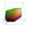
I have a couple animated GIFs below rotating this image looking from both above and also below the 3D image. The bounding shape ends up being two cubes with edge size of "Tolerance" one sitting at the min RGB corner and the other sitting in the max RGB corner. Those two cubes touch each other at just one corner point. Then, the two cubes are joined by an angled six sided pipe. Why so complex a shape. The real reason is not to have a complex shape. That is just the shape you get when using simple fast equations in software.

with their joined by a 6 sided pipe

Most of what one sees in PS is just 2D selections. An example of that is the prior posts by Tom Mann where he varied two colors in a gradient, one in X direction and the other in Y direction. If you take the selection boundary in the above picture and look at it end on to show only two of the dimensions of RGB values being selected you get a match with the selection shape demonstrated by Tom Mann:

2D tolerance boundaries.jpg

In this next image, I leverage the test case Mr Tom suggested. I create a two dimensional gradient (41 pixel on a side) with green shifting in X and red shifting in Y. I copied this 41 sq pixel dual gradient 13 times and increased the rlue value from 0 (on left) by 2 for each 41 sq pixel. I sampled with the magic wand tool in at the cross hairs (contiguous was turned off) and the selected pattern in each 41 sq box is shown.

If you stack up the selections from the left to the right, you end up with the same 3D shape I shared above.

PS-simulated-3D-selection.jpg

I have tested the above equations on a good number of examples and they all work. I don't mind trying out other suggested cases to see if they continue to fit.

Below are the 3D animated GIFS of the tolerance bounding box from the provided equations.
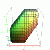
Animated Tolerance Top.gif Animated Tolerance Bottom.gif

I followed through on this for my own satisfaction and may not have value for others yet thought it was still worth posting in case anyone wanted more clarity on the analysis or suggestions on what else to try and test the equations for correctness.
 
Last edited:

Tom Mann

Guru
Messages
7,223
Likes
4,343
Beautiful work, beautiful explanation, John ! ! !

By Post #20, I had realized that the tolerance conditions were especially simple if expressed in RGB coordinates, and, of course, would look different in other coordinates. However, since I was already taking flack for being too mathematical, I didn't want to go into the details until people had become seat-of-the-pants comfortable with 1D and 2D visualizations of the tolerance regions, and then saw how the shape of the tolerance regions changed as one went from one coordinate system to another (eg, HSB, Lab, etc.). This is why I made the following qualitative statements / suggestions:

"...The interesting thing about all these holes is that the sides are almost perfect straight lines -- two sides parallel to the x-axis, two sides parallel to the y-axis, and the remaining two sides would be at exactly a 45 degree angle if I had scaled made the spectrum exactly square. This immediately tells us something about how the tolerance algorithm works. For example, if the "hole" had been a circle, it would have told us that the algorithm used the square root of the sum of the squares formula that I mentioned in my recent post. OTOH, if the hole only was four sided, it would have told us that the algorithm used the absolute value of the maximum of the differences in R, and in G, one of the other possibilities I mentioned in my earlier post.

However, one does not need to know the math that lies behind the visual effect to get an idea of how the tolerance slider works: you can check it for yourself by doing familiarization experiments like these. For example, as the next experiment, you could do a 2D gradient in RGB with hue on the horizontal axis and saturation on the vertical axis, and punch some test holes in this. If you do, you'll see that for small values of the tolerance, the holes are almost perfectly circular. This immediately tells us that the appropriate formula for small tolerances in this coordinate system WAS Euclid's classic formula for a circle: The square root of the sum of the squares of the two coordinates is a constant. ..."


That being
said, I'm glad that you and Mr.T took renewed interest in this topic and brought it to a clear, wonderful, fully quantitative conclusion.

Thank you both.

Tom M
 
Last edited:

MrToM

Guru
Messages
3,595
Likes
3,321
Unfortunately your images are not showing for me.

It looks like they need approval from a moderator which is confusing as a moderator has already replied to your post...so I'd assume approval had already been given.

Maybe another moderator could look into it please?

Regards.
MrToM.
 
Last edited:

IamSam

Administrator
Staff member
Administrator
Messages
22,754
Likes
13,268
MrToM, I'm not sure what happened to the images. I can't view them either. They will have to be re-uploaded.
 

MrToM

Guru
Messages
3,595
Likes
3,321
Thanks Sam, much appreciated.

Regards.
MrToM.
 

thebestcpu

Guru
Messages
2,994
Likes
2,760
The images I shared were never linked and worked before when uploaded. So I deleted the placeholders icons and re-uploaded them all to the last post. Hope they work now.
John Wheeler
 

Top